| Bulb Modelling Tutorial - Page 6 | |
 |
|
|
Step 14: |
|
 |
|
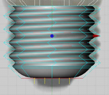
| Using Extrude Inner, pull the polys in a small distance. Then Extrude Inner again a very small amount to create a small ring of polys. Again this is to add detail holding edges to the HyperNurbs cage. Extrude the polys a small amount downwards. What we are doing here is forming the area where the insulator on the base starts. | |
 |
|
|
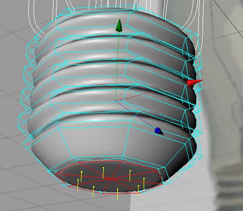
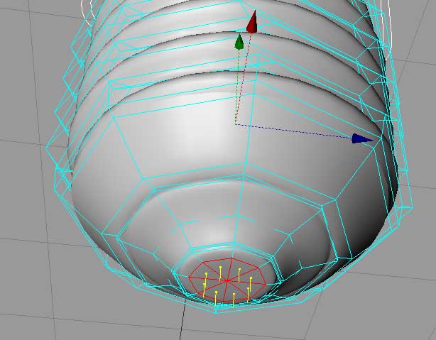
Bevel the polys again and then pull up on the green axis arrow to move the polys upwards slightly. This makes the bevel become more shallow. Bevel downards again, Then Etrude Inner a small ways, then Extrude down a small ways and finally Extrude Inner again. The result you are aiming for is shown above. What this series of steps does is model the insulator and the small "button"connector on the bottom of the light bulb. |
|
this site works best on Firefox: |